
M32 Internet of Things Arduino Yun compatible
M32 Internet of Things Arduino Yun compatible
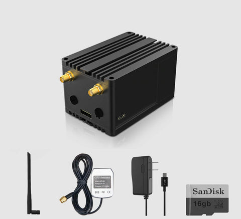
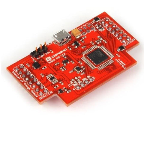
M32 Internet of Things module is designed for the ease of programming and installation of IoT projects. It is a plug-in module for MS14N-S and powered by an AVR ATmega32u4 microcontroller.
M32 is Arduino Yun compatible, it communicates with MS14N-S CPU via SPI and UART interface and provides the power / GPIOs via the 14 positions screw terminal on MS14N-S. M32 can be programmed by the latest Arduino IDE. The board type in Arduino IDE is "Arduino Yun".
With the combination of MS14N-S, M32 and Arduino Yun software, users can install Internet of Things projects in an easy and rapid way.
Features:
Internet of Things Gateway module to connect sensor network to internet.
Log sensor data and upload to remote server.
Control switch/relay from Internet.
Easy programming use Arduino IDE.
Program/update/ debug via WiFi network.
Specifications:
BEE socket1
| Microcontroller | ATmega32u4 |
| Operating Voltage | 5V |
| I/O voltage | 5V |
| 3.3V output channel | 1 |
| 5V output channels | 2 |
| SRAM | 2.5KB |
| Flash Memory | 32KB(of which 4KB used by bootloader) |
| EEPROM | 1KB |
| Clock Speed | 16Mhz |
| Digital I/O pins | 10 |
| Analog input channels | 8 |
| PWM channels | 4 |
| ESD-protection(IEC 61000-4-2) | |
| Over Voltage Protect | |
Power
M32 uses 5v power from ms14. The mega32u4 avr is powered by 5v as well. M32 provides 5V or 3.3V output power.
5V: The 5V output power pin is 1+ and 6+
3.3V: pin 6+ can be used for 3.3v power output, by using the VOUT_SEL jumper.
GND: 2 GND pins are available in 1- and 6-.
Input and Output Pins
Each of the 10 digital i/o pins on the m32 can be used as an input or output, using pinMode(), digitalWrite(), and digitalRead() functions. They operate at 5 volts. Each pin can provide or receive a maximum of 40 mA and has an internal pull-up resistor (disconnected by default) of 20-50 kOhms. In addition, some pins have specialized functions:
- TWI: 2 (SDA) and 3 (SCL). Support I2C / TWI communication using the Wire library.
- External Interrupts: 3 (interrupt 0), 2 (interrupt 1). These pins can be configured to trigger an interrupt on a low value, a rising or falling edge, or a change in value. See the attachInterrupt() function for details.
- PWM: 3, 6, 9, 10. Provide 8-bit PWM output with the analogWrite() function.
- LED: 13. The "heart beat" LED is connected to digital pin 13. When the pin is HIGH value, the LED is on, when the pin is LOW, it's off.
- Analog Inputs: A0 - A3, [A6, A8, A10, A11 (on digital pins 4, 6, 9 and 10)]. The m32 has 8 analog inputs, all of which can also be used as digital i/o. Each analog input provide 10 bits of resolution (i.e. 1024 different values). The analog inputs measure from ground to 5 volts.
- RESET_MS14:11(PB7): Bring this line LOW to reset the AR9331 microprocessor on ms14. Resetting the AR9331 will cause the reboot of the ms14. All the data stored in RAM will be lost and all the programs that are running will be terminated. The reset feature is deactivate by default to avoid error program on 11. Solder a 0ohm capacitor on R14 or short the two ends of this resister will active this feature.
ESD and Overvoltage Protection
Except 7+ and 7- , all other pins are Overvoltage and ESD protected following the standard IEC 61000-4-2.
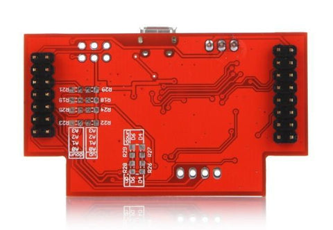
Internal Connectors
The M32 has two on board connectors which are reserve for further development.
- I2C Connector: This 1x4 (2.54mm) connector has SCL/SDA/5V/GND pin out, it can used to hook up a small I2C PCB and place into MS14.
- J2 Connector: This connector is reserved for further process the signal on 7+ and 7- pins.
USB Connector
M32 has a micro USB connector and can act as standard USB COM device. This USB connection can be used to upgrade firmware or debug the software via serial monitor on Arduino IDE.
Documents:
Detail technical info in M32 WiKi Page
Schematic and pcb (pdf) (Eagle version)