WiFi NINA click - MikroElektronika Powerful Standalone u-blox WiFi Module
WiFi NINA click - MikroElektronika Powerful Standalone u-blox WiFi Module
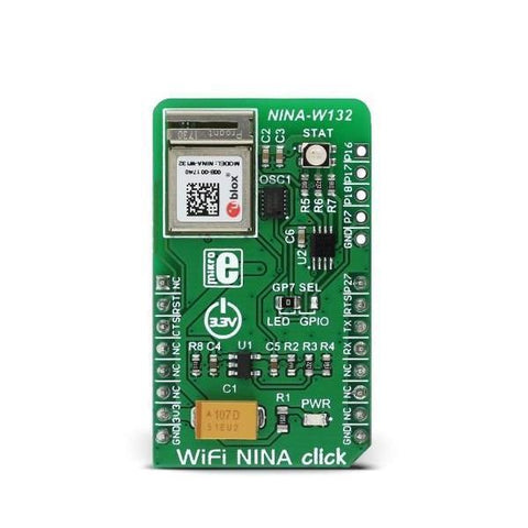
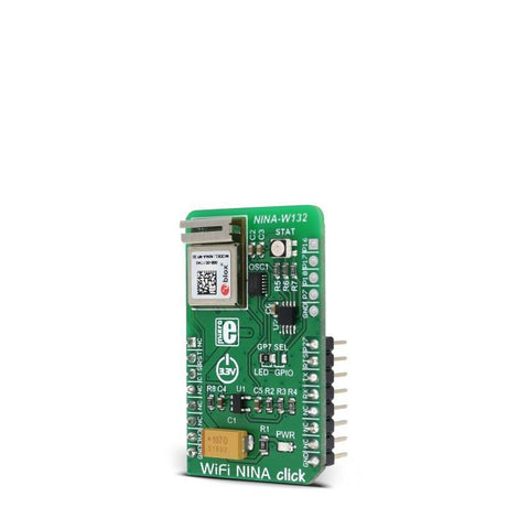
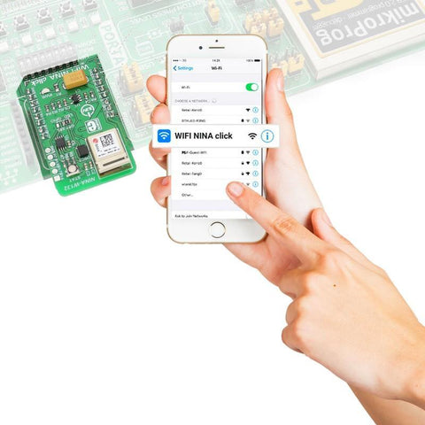
WiFi NINA click is a powerful standalone WiFi module, equipped with the state-of-the-art NINA-W132 module from u-blox, that can be easily configured with the u-blox s-center software, using AT commands. WiFi NINA click offers a complete WiFi stack, it is really easy to use and provides a simple way to build secure IoT applications.
This WiFi module integrates a powerful dual 32bit MCU and a radio for wireless communication. It comes with preprogrammed application software that supports 802.11b/g/n in the 2.4 GHz ISM band. WiFi NINA click also features an RGB diode, which is used to display the connection status of the device. These features make this click a perfect and secure IoT solution. It can also be used for any type of WiFi networks, medical and industrial networking, home/building automation and other applications that require wireless network access.
How does it work?
The module used on WiFi NINA click incorporates powerful dual MCUs and a radio for wireless communication. Two 32bit MCUs, operate at the maximum frequency of 240 MHz. The module is also equipped with an internal PIFA antenna, specially optimized to fit the NINA form factor.
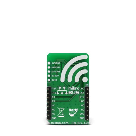
WiFi NINA click uses UART to communicate with the MCU. It supports a wide range of UART baud rates, including some less common rates, up to 921600 bps. The data transfer pins (RX and TX) are routed to the corresponding mikroBUS™ pins for easy interfacing with the host MCU. Besides these pins, this click has several more pins routed both to mikroBUS™ and onboard pads. 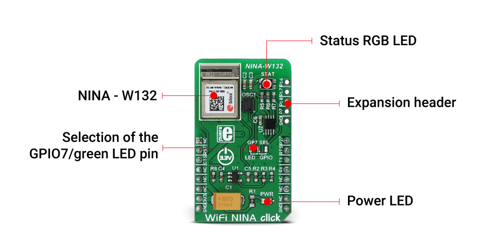
u-blox company offers a software tool that can be used to configure WiFi NINA click from the OS. To use this software, the UART signal from the click board™ should be converted to the USB compatible signal, using any of the UART to USB converters available, such as click USB adapter, or USB to UART click. It should be noted that the WiFi NINA pins should be set to certain states which enable the UART connection (more information can be found in the NINA-W132 datasheet as well as in the demo application included in the click library)
RST pin of the mikroBUS™ is routed to the Reset pin of the NINA-W132. It can be used to reset the module. Bringing this pin to a LOW logic level will cause a reset and will put this device into a very low power consumption mode. This pin is in an open-drain configuration, and it is internally pulled to a HIGH logic level.
CTS and RTS signals of the NINA-W132 module are routed to the CS and INT pins of the mikroBUS™, respectively. These pins are used for implementing a hardware flow control.
DTR and DSR pins are used for configuring the WiFi NINA click. These pins are not routed to the mikroBUS™, but are routed to the onboard pads instead, so they can be used externally.
- Enter command mode
- Disconnect/toggle connectable status
- Enable/disable the rest of the interface
- Enter/ wake up from the sleep mode
An RGB LED is used to signalize the status of the device. Green LED status pin is routed to the onboard SMD jumper. It can be used to route this signal to the RGB LED, or the SWITCH 1 pad on the edge of the click board™. This LED changes colors depending on the status of WiFi NINA click:
- Data mode - IDLE - Green
- Command mode - IDLE - Orange
- Data/Command mode - CONNECTING - Purple
- Data/Command mode - CONNECTED - Blue
SWITCH 1 and SWITCH 2 pins are routed to the pads on the edge of the click board™. As already explained, the SWITCH 1 function is multiplexed with the Green LED status pin. To use its SWITCH 1 functionality, GPIO7 SMD jumper has to be switched to the correct position (GPIO). Note that in this case, the green component of the RGB diode will be disconnected and the status LED colors will be changed. These pins can be used to set the following options:
- If SWITCH_2 is driven low during startup, the UART serial settings are restored to their default values
- SWITCH_2 can be used to open a connection to a peripheral device
- If both SWITCH_1 and SWITCH_2 are driven low during startup, the system will enter the bootloader mode
- If both SWITCH_1 and SWITCH_2 are driven low during startup and held low for 10 seconds, the system will exit the bootloader mode and restore all settings to their factory defaults
For a low power operation, an external low power oscillator (LPO) has to be added. WiFi NINA click features the SG-3040LC, an external oscillator with the controllable output voltage, supplied by the AP7331 LDO regulator. It outputs 32.768 kHz signal with an amplitude of about 0.7V.
The demo application available for this click demonstrates the usage of the WiFi-NINA click library functions and the proper initialization sequence. It can be used as a reference for any custom design. The libraries contain simple and easy to use functions for sending AT commands to the NINA-W132 module and getting the responses back, saving users from having to write rather complex code for the response interception and other time-consuming software elements.
Specifications
| Type | Wi-Fi |
| Applications | WiFi NINA click is a perfect and secure IoT solution, but it can also be used for WiFi networks, medical and industrial networking, home/building automation and other applications that require wireless network access |
| On-board modules | NINA-W132 WiFi module from u-blox company |
| Key Features | WiFi NINA click offers a complete WiFi stack which is really easy to use and provides a simple way to build secure IoT applications. It uses the UART interface for the communication with the host MCU |
| Interface | GPIO,UART |
| Input Voltage | 3.3V |
| Click board size | M (42.9 x 25.4 mm) |
Downloads