DC Motor 8 click - MikroElektronika Half-bridge MOSFET DC Motor Driver
DC Motor 8 click - MikroElektronika Half-bridge MOSFET DC Motor Driver
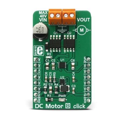
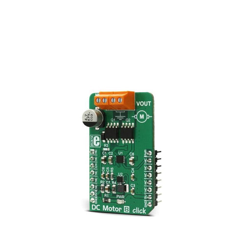
DC Motor 8 click is a DC motor driver. It can drive simple DC motors with brushes, providing them with a significant amount of current and voltage up to 40V. The click has one control input, that uses the PWM signal from the host MCU. It uses the half-bridge topology to regulate the speed of the motor rotation, employs advanced dead-time circuitry that monitors the output stage, providing maximum switching efficiency and features an advanced technique to avoid shoot-through currents.
Features, such as high-efficiency factor, low overall power consumptions and complete isolation of the output stage, enable this device to be used in various battery operated handheld tools, fans and in general - whenever a powerful and reliable DC motor driver is required.
How does it work?
DC Motor 8 click relies on the MIC4605, 85V half-bridge MOSFET driver with adaptive dead time and shoot-through protection, from Microchip. This IC uses the input on its PWM pin to regulate the switching state of the output MOSFETs. The fact that it is 85V tolerant, allows for a substantial margin against kickback voltage that appears as the result of the rotation of the motor. In practice, at least twice the power supply used for the motor should be considered as a safe margin. This IC has more than enough to accommodate for the maximum voltage allowed on its input, which is 40V.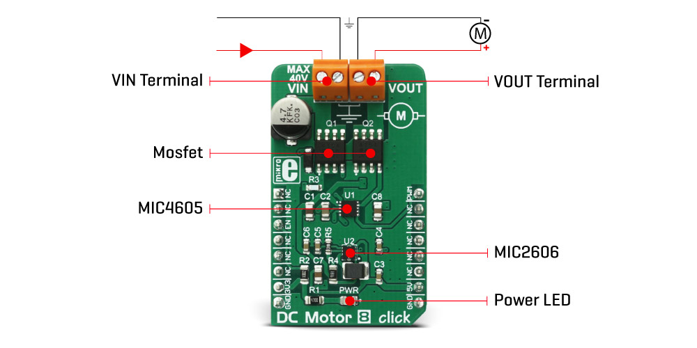
DC Motor 8 works in a half-bridge topology, which means that it can run the connected motor in one direction only. However, the polarity of the connected motor can be flipped, which will result in a change of the rotational direction of the motor. The connected input voltage must not be reversed, it has to stay connected as labeled on the PCB. Although the maximum input voltage rating is 40V, it is a good practice never to supply the motor with the maximum allowed voltage, as it may result in overheating of the MOSFETs and other components, depending on the used motor and the mechanical load it is exposed to. The device should never be pushed to work at maximum allowed ratings.
While the PWM input is at the HIGH logic state, HO output pin that drives the high side power MOSFET is active and the circuit is closed through the high side power MOSFET, motor coil, and the ground. When the PWM input signal goes LOW, it forces the HO output to also go low, within about 35ns. The HS pin monitors the driver state - when the HS voltage drops under 2.2V, the high side MOSFET is closed and after a short delay (about 35ns of rise time) LO output is activated. A further drop of the HS voltage causes a latch, which can be only reset by the PWM signal HIGH logic level. If the HS level fails to drop under 2.2V, the internal 250ns delay is activated and the HS pin is latched anyway, after that. This prevents the HS ringing to cause an undetermined state of the LO output. When the PWM signal goes HIGH again, it will force the LO output to a LOW within another 35ns, after which the HO pin can start going into the HIGH level again.
This mechanism ensures that no shoot-through ever occurs. Shoot-through happens when both MOSFETs are active and when the current goes right through them, from the power supply to the ground, causing dissipation, ringing and even damage in some cases.
Besides the PWM pin routed to the mikroBUS™, the EN pin used to enable the device is also routed to the mikroBUS™ CS pin. Logic HIGH will set the device to work in normal mode, while LOW logic level will put the device into the power conservative shutdown mode. This pin is pulled HIGH with the onboard resistor.
The VIN power terminal used to provide up to 40V of power supply for the DC motor, is completely isolated from the driver circuitry. However, to operate correctly - the driver has to provide enough voltage for activating the MOSFETs. For this purpose, DC Motor 8 click employs a buck converter made of MIC2606, a 2MHz boost regulator from Microchip. The boos regulator circuitry provides 12V out of 5V from the mikroBUS™, which allows for ideal MOSFET switching conditions, keeping the resistance through the MOSFET (RDSON) at optimal levels.
VOUT terminal is used to connect a load. A small to medium powered DC motor with two connection points and up to 40V can be used with this click board™. The voltage at the VIN terminal is used to power the motor on, while the click itself is being powered from the mikroBUS™ voltage rails. For a proper operation, both 3.3V and 5V voltages must be present on the mikroBUS™.
Specifications
| Type | DC |
| Applications | It can be used in various battery operated handheld tools, fans and in general - whenever a powerful and reliable DC motor driver is required. |
| On-board modules | MIC4605, 85V half-bridge MOSFET driver with adaptive dead time and shoot-through protection and MIC2606, a 2MHz boost regulator, both from Microchip |
| Key Features | DC Motor 8 features a good switching efficiency, low overall power consumptions and complete isolation of the output stage. It employs advanced adaptive dead-time and intelligent shoot-through protection mechanisms. |
| Interface | GPIO,PWM |
| Input Voltage | 3.3V or 5V |
| Click board size | M (42.9 x 25.4 mm) |
Downloads