DIGI POT 3 click - MikroElektronika 1024 Steps Digital Potentiometer
DIGI POT 3 click - MikroElektronika 1024 Steps Digital Potentiometer
DIGI POT 3 click is a versatile and feature-rich digital potentiometer click with 1024 steps and an internal non-volatile memory (EEMEM), which can be used for storing the wiper position, but also for storing various user data. The user EEMEM area has 14 words, each with 16bit length. The Click board™ can be used with both unipolar and bipolar signals, selectable by onboard SMD jumpers. The wiper position can be increased or decreased linearly or by the logarithmic scale (6db/step) with a single command. A special scratch register allows direct programming of the wiper position. It can be stored in the non-volatile memory and on the power on, it is automatically restored. This means that the device restores its last position after the power on - just like its mechanical counterpart.
The main advantage of the digital potentiometers over the mechanical ones is that they can never wear out. The wiper position can be precisely programmed, and the wiper contact with the resistive coating can never be compromised by the influence of dirt or moisture. Due to its low THD and good bandwidth, it can be used for digital volume control or a precise gain and offset adjustment. It can also be used as the LCD digital contrast control, and generally - whenever a precise digital potentiometer is required.
How does it work?
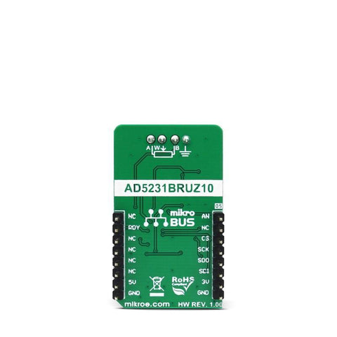
This Click board™ carries the AD5321, a 1024-position (10bit) digital potentiometer with a non-volatile memory (EEMEM), from Analog Devices. As already mentioned, this digital potentiometer has many features that make it a superior choice over the classic, mechanical potentiometers. It offers the solid state reliability, high precision, an additional storage non-volatile (NV) memory cells and most importantly - it can be digitally controlled by an MCU via the high-speed SPI interface, with its pins routed to the mikroBUS™. Analog Devices Inc. offer several sub-types of the same IC, but the DIGI POT 3 click uses the one labelled as AD5231BRUZ10, meaning that it has 10KΩ of resistance between the potentiometer end-points.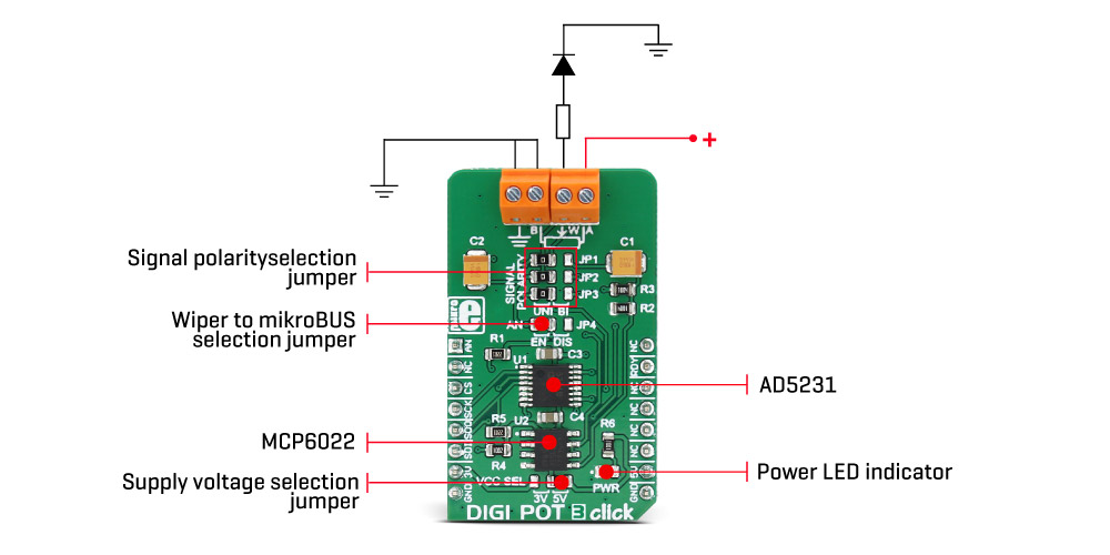
One of its distinctive features is to refresh its wiper register (called RDAC in the device datasheet) after the power on, making it possible to restore the wiper position on power-up, just like the mechanical counterpart. The wiper position register (RDAC) is not automatically written to the EEMEM because this type of memory has a limited number of write cycles, which is the limitation of the technology itself. For this reason, once the position has been established, it can be stored to EEMEM by a command (Command 0x2 - Store RDAC setting to EEMEM). The AD5321 IC is factory pre-programmed to set the wiper at the middle position after the power-on, but this can be overwritten by storing a custom position with the aforementioned command.
Besides storing the RDAC register to the EEMEM, it is possible to store 14 more words, each 16 bits long. This EEMEM area can be used for any purpose - lookup tables, data for other components, or system identification information. Writing to EEMEM takes some time, during which the AD5231 IC is non-responsive. This time is about 25ms and the end of this operation is signalled by the RDY pin of the AD5321 IC, routed to the INT pin of the mikroBUS™ - labelled as the RDY. When the read to, or write from EEMEM cycle is done, this pin pulses to a LOW logic level. It is otherwise pulled to a HIGH logic level by an on-board pull-up resistor.
For the complete list of commands and addresses, please refer to the AD5321 datasheet. However, MikroElektronika provides a library that contains functions compatible with the MikroElektronika compilers, which can be used for simplified programming of the DIGI POT 3 Click. The library also contains an example application, which demonstrates their use. This example application can be used as a reference for custom designs.
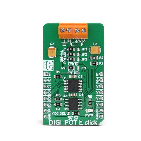
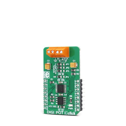
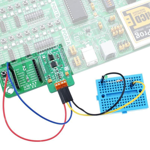
The Click board™ is equipped with an edge screw terminals, which are used to connect the Click board™ to the external electrical circuit. They offer a secure connection to the external electrical circuit. A small print of a potentiometer electrical symbol illustrates how to connect these terminals properly: Inputs labelled as A and B are the endpoints of the digital potentiometer, while W is the wiper. Lastly, GND symbol is for connecting the ground of the circuit where the potentiometer will be used.
DIGI POT 3 click allows using of both unipolar and bipolar signals. The potential across the positive and the negative power supply pins define the boundary conditions for a proper digital potentiometer operation. Supply signals present on the A, B, and W terminals that exceed this range are clamped by the internal forward-biased diodes. Since this Click board™ is intended to be used on the mikroBUS™, the power supply voltage of the AD5321 is +3.3V or +5V, selectable by an onboard SMD jumper labelled as VCC SEL. This makes it possible to work with the voltage range between 0 and VCC. By utilizing an additional circuitry, it is also possible to work with the bipolar (AC) signals that range between –VCC/2 to VCC/2, which can be useful for interfacing the digipot to an audio source.
Since there are no negative power supplies available on the mikroBUS™, the Click board™ uses the MCP6022, a rail-to-rail, 10 MHz onboard operational amplifiers from Microchip, in order to support operation with bipolar signals. It is used as an inverting amplifier with a unity gain - a buffer. There are several onboard SMD jumpers, used to route the signal so it passes through the buffer, instead of being fed directly to the AD5321 IC. A group of SMD jumpers labelled as SIGNAL POLARITY is used to patch the signal to a proper route: setting all these jumpers to the LEFT position will connect the terminal inputs directly to the AD5231 IC, allowing unipolar signals ranging from 0 to VCC to be connected. Moving all these jumpers to the RIGHT position will route the input signal through the buffer, allowing bipolar signals to be used, in the range between –VCC/2 to VCC/2, as explained in the previous paragraph. The SMD jumpers should be moved all to the LEFT or to the RIGHT position, as leaving some of them in the opposite position than the others can render the device unusable.
The AN pin can be used as an auxiliary wiper output if routing of the wiper back to the mikroBUS™ is required. This pin can be completely disconnected from the mikroBUS™ by moving the appropriate SMD jumper, labelled as AN to the RIGHT position. This will not affect the presence of the wiper output on the output terminal.
Specifications
| Type | Digital potentiometer |
| Applications | It can be used for digital volume control or a precise gain and offset adjustment. It can also be used as the LCD digital contrast control, and generally - whenever a precise digital potentiometer is required. |
| On-board modules | AD5321, a 1024-position digital potentiometer with non-volatile memory (EEMEM), from Analog Devices; MCP6022, an R2R input/output, 10 MHz Op Amp, from Microchip. |
| Key Features | Accurate positioning of the wiper via the 1024 different steps, non-volatile EEPROM memory used for recalling the wiper position and custom data storage, simple commands for linear/logarithmic wiper control, can accept both bipolar and unipolar signals. |
| Interface | Analog,SPI |
| Input Voltage | 3.3V,5V |
| Click board size | M (42.9 x 25.4 mm) |
mikroSDK
This click board is supported by mikroSDK - MikroElektronika Software Development Kit. To ensure proper operation of mikroSDK compliant click board demo applications, mikroSDK should be downloaded from the LibStock and installed for the compiler you are using.
For more information about mikroSDK, visit the official page.
Downloads