DIGI POT 5 click - MikroElektronika Digital Quad Potentiometer
DIGI POT 5 click - MikroElektronika Digital Quad Potentiometer
DIGI POT 5 click is a digitally controlled quad potentiometer, with the resistance of 10KΩ. It has an 8bit wiper step resolution, which allows the wiper to take 257 different discrete positions (across 256 internal resistors). The digital wiper position can be controlled via the SPI interface. DIGI POT 5 click features a durable EEPROM non-volatile (NV) memory for storing the wiper position. The content of the wiper register memory located in the NV memory is copied to the actual wiper registers after the power-on or reset state, so the device acts similar to its mechanical counterpart, recalling its last used wiper position after being powered on. The device also features the WiperLock™ technology, which effectively locks the wiper position in place.
DIGI POT 5 click has a multitude of practical uses in electronic circuits. The most popular uses include precision calibration of set point thresholds, sensor trimming, LCD contrast adjustment, audio attenuation, an adjustable gain for amplifiers and offset trimming. DIGI POT 5 click can be used to replace the common mechanical trim pot, in a wide range of different applications where the operating voltage stays within the limits.
How does the click work?
DIGI POT 5 click features the MCP4361, an 8bit quad digital potentiometer from Microchip. This is a very versatile quad digital potentiometer, controlled via the SPI interface. The device has four integrated digital potentiometer sections, which consist of a string of resistors - serially connected, with digitally controlled analog switches, used to connect the wiper terminal position. The wiper position value of 0x000h corresponds to the lower end of the resistors ladder, while 0x100h corresponds to the upper end of the resistors ladder. These values can be written in the volatile wiper registers, one address for each of the four wipers.
Each of the four wipers can be controlled in several ways. Writing data directly to the volatile wiper register will result in moving the wiper to the specified location. Wiper value can also be incremented or decremented, by writing data to the incrementing or decrementing registers, providing that the wiper is not locked and that the wiper register value is not 0x000h (prevents further decrease) or above 0x100h (prevents further increase). If the wiper register is set to a value greater than 0x100h, both increasing and decreasing commands will be disregarded. The incrementing and decrementing registers allow for less overhead if the wiper position has to be increased or decreased, making it easy to interface with the rotary encoder applications, for example.
The MCP4361 also features the WiperLock™ function, which prevents further changes of the wiper position, effectively locking the wiper in place. To enable this functionality, the CS pin needs to be pulled beyond the predefined voltage level threshold (8.5V to 12.5V). When this happens, the device will enter into the high voltage communication mode (HV mode), and the WiperLock™ functions can be accessed. The click board has a dedicated high voltage input pad (VIHH), which can be used to drive the CS pin with the appropriate voltage level when the HV mode is required.
The resistor ladder network can be completely disabled by writing to the terminal control registers. This allows to effectively disconnect the potentiometer terminals from a circuit, reducing the power consumption of both the MCP4361 and the electrical circuit the IC is used in. The terminal control registers can also be used to switch each of the wiper terminal and the two resistor terminals, separately. There is also a STATUS register, used for storing various status related information, such as the WiperLock™ status, EEPROM write protect status and so on.
The EEPROM memory is used to hold the wiper data, even after the power down. There are several (five) general purpose 9bit addresses and 4 NV wiper register addresses that are copied to the wiper register addresses after the restart or power-up, allowing the device to resume the wiper position from a previous, stored state. By default, the data registers are zeroed out, while the NV wiper registers hold the middle scale position for the wiper..jpg)
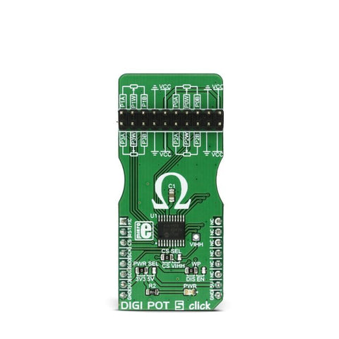
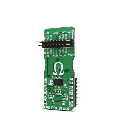
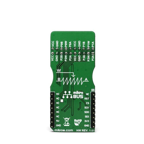
DIGI POT 5 click has one 2x10 pin standard, 2.54mm pitch header used to connect the four potentiometer terminals. There are three SMD jumpers onboard:
The SMD jumper labeled as WP is used to set the WP pin state of the MCP4361. The WP pin is used as the hardware EEPROM write protection, along with a software WP bit of the STATUS register (writable in HV mode only). Both the hardware WP pin and the software WP bit has to be set to disabled mode, in order to write to EEPROM.
The SMD jumper labeled as PWR SEL is used to select the power supply voltage - 3.3V or 5V. This also affects the logic voltage levels, used for the SPI communication.
The SMD jumper labeled as CS SEL is used to select the CS pin voltage level. If the HV mode is required, this jumper should be moved to the VIHH position, so that the externally connected 8.5V to 12.5V power source can be used to pull up the CS pin. If HV mode is not required, this SMD jumper should stay at the default position (CS). Note that while in the HV mode, the CS pin is used the same way as with the regular SPI communication, with a difference in logical levels - the HV mode logical HIGH is at least 8.5V.
Specifications
| Type | Digital potentiometer |
| Applications | DIGI POT 5 can be used for precise calibration of set point thresholds, sensor trimming, LCD contrast adjustment, audio attenuation, an adjustable gain for amplifiers and offset trimming |
| On-board modules | MCP4361 8-Bit quad digital POT with non-volatile Memory and SPI interface |
| Key Features | Digitally controlled quad potentiometer with 257 discrete wiper positions, SPI communication protocol, WiperLock™ feature, and user programmable EEPROM memory |
| Interface | GPIO,SPI |
| Input Voltage | 3.3V or 5V |
Downloads