Multimeter click - MikroElektronika Voltage, Current, Resistance, & Capacitance
Multimeter click - MikroElektronika Voltage, Current, Resistance, & Capacitance
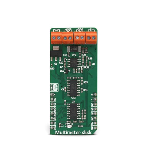
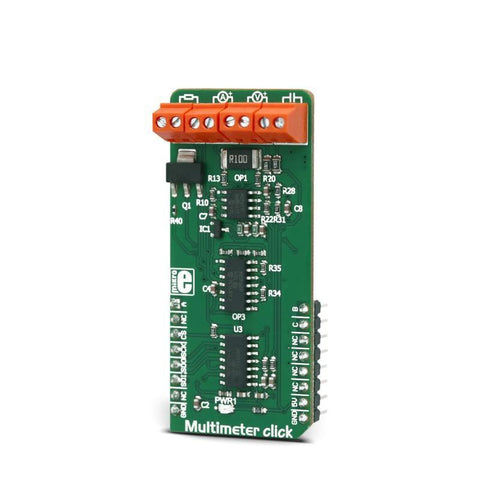
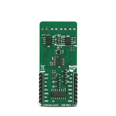
Multimeter click is a Click board™ designed to measure voltage, current, resistance, and capacitance properties of the components, connected to the input terminals. Each property measurement is done on a separate terminal. Each measurement section conditions the input signal from the respective input terminal and forwards it to a four-channel 12-bit A/D converter. All the inputs are equipped with the differential amplifiers, that allow both positive and negative signals to be measured. By utilizing the binary-to-decimal converter IC, it is possible to select the optimal range for the resistance measurement. Low internal resistance of only 0.1Ω for the current and high resistance of 1MΩ for the voltage measurement section, ensure no interferences with the measured circuitry, caused by this Click board™.
Since there are four distinctive properties that can be measured with Multimeter click which all require different measuring techniques, several different ICs had to be used on the Click board™. Starting with the high-quality, low noise A/D converter as the primary component, all the way to the input operational amplifiers, all components were hand-picked to ensure accuracy. Even the lowest amounts of noise, distortion, or crosstalk, might have a great impact on the overall accuracy of the measurement. This Click board™ can be used as the development platform for measurement applications, or simply as a very compact, accurate, and handy digital multimeter device.
How does it work?
The operation of this Click board™ is managed by several different ICs, including operational amplifiers, NE555 timer, BCD decoder, frequency to voltage converter, and finally an A/D converter (ADC). The auxiliary ICs for providing -5V and the ADC referent voltage of 2.048V, are also present. The Click board™ uses the MCP3204, a four-channel, 12-bit ADC with an SPI interface, from Microchip. The conditioned signals are routed to each input of the ADC. The input channel is selected by the initial SPI command, after the #CS (chip select) pin becomes LOW. Three configuration LSBs are used to set the sampling channel (D0-D2), while the fourth bit (D3) sets the mode. The ADC is routed to work with single-ended inputs, and therefore this bit should always be set as 1.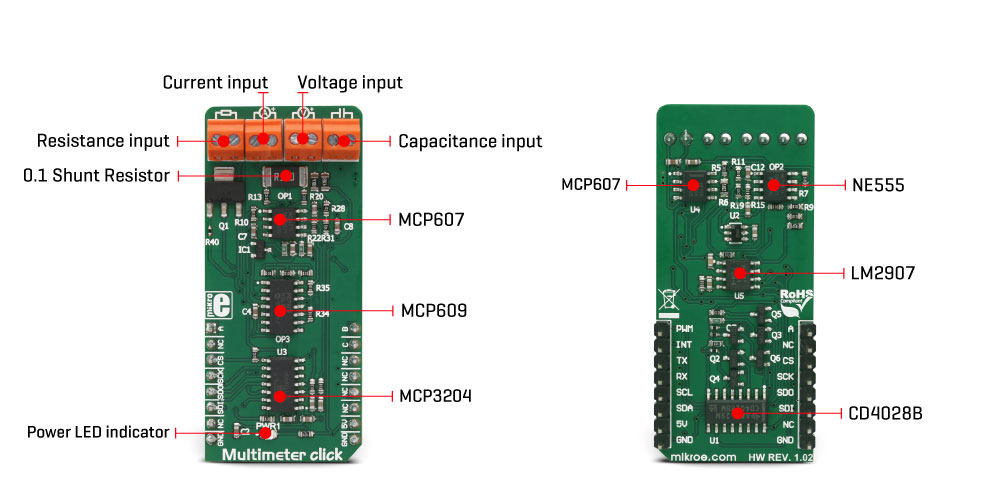
Current measurement
A differential input amplifier is used to amplify the voltage difference across the shunt resistor. One half of the MCP607, a dual CMOS op-amp from Microchip is used for that purpose. The value of the shunt resistor is 0.1Ω, which allows up to 1A of current to be measured. Since the ammeter is connected in series, the shunt resistor has to be of a very small value, in order to prevent interferences with the measuring circuitry. This is one of the basic requirements of the ammeter. The voltage drop at the shunt is amplified by the differential op-amp (by the factor of 10), and the op-amp output is routed to one of the ADC inputs, which is labeled I on the schematic. The op-amp uses half of the referent voltage (Vref) as the virtual GND so that both positive and negative values can be converted.
Voltage measurement
When measuring a voltage, the internal resistance of the voltmeter has to be large, since it is connected in parallel with the component across which the voltage is measured. The Click board™ uses the MCP609, a quad CMOS op-amp, configured as dual-buffer and a differential amplifier. It is the same device as the MCP607, but with four integrated op-amps. Two integrated op-amps work as buffers with voltage dividers at their non-inverting inputs, while the third op-amp acts as the actual differential amplifier. Again, the op-amp uses the virtual GND, set at half of the Vref for the output biasing. This allows both negative and positive voltage potential to be measured, across the load connected at the input terminal. The output from the differential amplifier is routed to the ADC input labeled as U.
Resistance measurement
Measurement of the resistance consists of a voltage divider, which is formed by an unknown resistance connected to the resistance measuring terminal, and a selectable, known, reference value resistor. The voltage applied to the voltage divider is also known (Vref). The middle tap of the divider is routed directly to the ADC input pin labeled as R, allowing reading of the voltage which directly depends on the unknown resistance. The CD4028B, a BCD decoder IC from Texas Instruments is used to select the correct reference resistance range. Three input pins (A, B, C) of the CD4028B are used to activate one of 6 MOSFET gates, via the logic states of the AN, PWM and INT pins of the mikroBUS™, which connect the desired reference resistor to the measuring circuit.
Capacitance measurement
The capacitance property can be measured with many multimeters commercially available, but it is not something included in some cheaper models. It consists of the NE555 precision timer, which is configured as an astable multivibrator. It generates impulses, set to about 50% duty cycle, with the frequency of 585Hz. This signal is converted by the LM2907MX, a frequency to voltage converter from Texas Instruments. The unknown capacitance is connected to the threshold input of the NE555, affecting the frequency of the pulses. The LM2907MX responds by changing the DC output voltage, which is fed to a differential op-amp. The higher the connected capacitance, the lower the LM2907 output becomes. The DC signal is then passed through another differential amplifier and routed to the ADC input labeled as CU, so it can be sampled by the ADC and read via the SPI.
Software
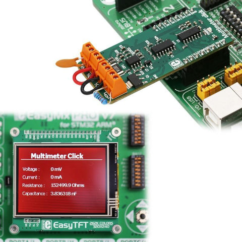
A software (or a firmware) running on the host MCU is required, in order to transform raw ADC readings and show them on an output device (UART, display...) The library provided with the Multimeter click offers a set of functions, which output straight-forward measurements and can be implemented easily in a custom code. Before actual measurement, as a part of the device initialization procedure, a calibration routine needs to be performed, so that components tolerances are taken into an account. Therefore, there should be nothing connected at the input terminals of the Multimeter click, until it is initialized by the software. The provided example application demonstrates how to use this click board, so it can be used as a starting point for future development.
Specifications
| Type | Measurements |
| Applications | This Click board™ can be used as the development platform for measurement applications, or simply as a very compact, accurate, and handy digital multimeter device |
| On-board modules | MCP607 dual CMOS op-amp, MCP609 quad CMOS op-amp, MCP3024 12-bit ADC, by Microchip; NE555 timer, CD4028 BCD decoder, LM2907 freq to voltage, by Texas Instruments; MAX6106 2.048 V reference, by Maxim Integrated |
| Key Features | Low internal resistance for the current and high internal resistance for the voltage, five different resistance measuring ranges, capacitance measurement, separate inputs for each measured property |
| Interface | GPIO,SPI |
| Input Voltage | 5V |
| Click board size | L (57.15 x 25.4 mm) |
Downloads