ATA6570 click - MikroElektronika High-Speed CAN Transceiver
ATA6570 click - MikroElektronika High-Speed CAN Transceiver
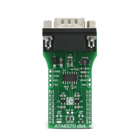
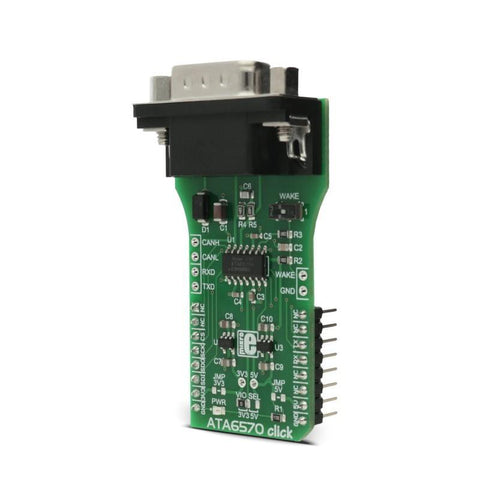
ATA6570 click is a CAN Partial Networking interface board. The click carries the ATA6570, a high-speed CAN transceiver that interfaces a Controller Area Network (CAN) protocol controller and the physical two-wire CAN bus. This IC has some unique features that make it a perfect choice for any embedded CAN application.
It supports both CAN and CAN FD protocol types, partial networking, local and remote wake up, an SPI interface for internal registers configuration, and it features six operating modes as well as the under voltage and overtemperature protection. The power consumption is taken to a minimum, as the ATA6570 can power down the entire system until a valid wake-up frame is received - even on a busy CAN bus. The car battery supply pin and the CAN bus pins are protected from various interferences and voltage instabilities, typically observed in automotive systems. ATA6570 click provides you with a robust and reliable CAN bus interface.
How does it work?
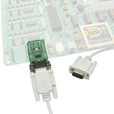
ATA6570 click uses the ATA6570, a standalone high speed CAN transceiver IC from Microchip, with the partial networking support. This IC supports both CAN and recently established CAN FD protocols, up to 1Mbit/s and 5Mbit/s respectively. The communication inside the CAN bus is differential and it is performed through the twisted pairs with the characteristic impedance of 120Ω. The differential lines are driven by the CANH and CANL drivers. This provides robustness and immunity to electromagnetic interferences, typically observed in automotive systems. The ISO 11898 standard defines a signal line of twisted-pair cable as the network topology, terminated by the resistors with the characteristic impedance of the CAN bus (120Ω) at both ends - in order to prevent signal reflection.
The dominant/recessive states are used for the message priority arbitration - the node which transmits signal with the higher priority (the lower the binary message identifier number, the higher the priority) will win the arbitration, and the node with the lower priority will abort the transmission, waiting for the bus to become available again. Since the high logic level on the CAN line is considered as the recessive, the TXD line has the internal pull-up resistor, making the ATA6570 device stay in recessive mode if the pin is left floating.
The ATA6570 device can be driven in the recessive or the dominant state with the TXD pin: when the TXD pin is at the VCC level and the device works in Normal mode, the drivers at the CANH and CANL pins are turned off. These pins are biased at 2.5 (VCC/2), with respect to the GND, provided by the internal autonomous bus biasing circuitry and the CAN driver is in recessive state. Pulling the TXD pin to the GND will activate the CANH and CANL drivers and set the bus to the dominant state. A TXD dominant timeout timer is started when the TXD pin is set to low. If the low state on the TXD pin persists for longer than the predetermined time, the transmitter will be disabled, releasing the bus lines to the recessive state. This function prevents the hardware or software failure from driving the bus lines to a permanent dominant state, blocking all network communications. When the device is in the Sleep or Unpowered mode, the drivers will become highly resistive, rendering the device passive and completely ignored by the CAN bus network.
Although the RXD and TXD lines are interfaced with the microcontroller, the SPI bus is used to set the internal registers, such as the partial networking registers and other status and configuration related registers. The provided MikroElektronika library contains functions used to easily set the parameters via the SPI bus, as well as to establish the communication with the nodes.
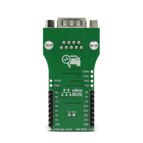
Partial networking allows selective wake-up of ATA6570 click. Dedicated predefined frames can wake up the device if it is configured to accept these frames. For this reason, when the device is in the Standby or Sleep mode, it will still actively monitor the bus for those frames. The wake-up CAN frame ID and data can be set by SPI. Besides waking up the device by the partial networking feature, the device can also be woken up by a remote wake-up pattern on the CAN bus or with the onboard switch connected to the WAKE pin of the ATA6570 IC. Another wake-up source can be the SPI command, for those modes where the SPI module is active, and the remote wake-up pattern on the CAN bus.
When in Sleep, Microcontroller Reset or Power Off mode, the INH pin which is routed to the external regulators, will be turned off, reducing the power consumption of the external elements.The #SHDN (shutdown) pins of the two LDO regulators, which are found on ATA6570 click, are connected to the INH pin. Both regulators take power from the car battery connector (VS pin), providing 5V and 3.3V for custom needs. Outputs of those LDOs are routed via the SMD jumpers that can be populated so that the LDOs can be used to power up the mikroBUS™ 3.3V and 5V power rails. However, it should be noted that MikroElektronika does not advise powering up own systems this way - that is why these jumpers are left unpopulated by default.
Overtemperature mode is activated when the temperature of the device becomes too high and the device was previously working in Normal mode. The ATA6570 provides two levels of overtemperature protection. When the first temperature level threshold is reached, an alarm in a form of an interrupt on the RX pin (if set) and an appropriate status bit. If the temperature rises even more, the device will shut down the CAN drivers.
Microcontroller Reset mode utilizes an integrated watchdog. When the watchdog event occurs, it will trigger a pulse on the INH pin - this pin will be turned off for a predetermined period of time, performing a power cycle reset on all devices connected via the ATA6570 click LDOs. This is meant as a power cycle reset measure for a custom system, powered via the mikroBUS™ socket.
The onboard SMD jumper labeled as the VIO SEL is used to select which voltage rail of two LDO regulators will be used as the logic voltage level (SPI, UART). It offers voltage selection between 3.3V and 5V so that the click board™ can be interfaced with both the 3.3V and 5V capable MCUs.
Specifications
| Type | CAN |
| Applications | ATA6570 click provides a robust and reliable CAN bus interface. This click is a perfect choice for any embedded CAN application. |
| On-board modules | ATA6570, standalone high speed CAN transceiver that interfaces a Controller Area Network (CAN) protocol controller and the physical two wire CAN bus |
| Key Features | The ATA6570 supports both CAN and CAN FD protocols, supports local and enhanced remote wake up, and it has very low power consumption during Standby and Sleep modes. CAN I/O pins are protected against conditions found in automotive applications. |
| Interface | SPI,UART |
| Input Voltage | 3.3V or 5V |
| Click board size | L (57.15 x 25.4 mm) |
Downloads